ZONE INSPECTOR
Overview
The Zone Inspector is an essential dialogue based analysis tool for all the planes on your board. It also provides a really fast way to locate a zone (power plane) and a direct means to edit the zone properties. You launch the Zone Inspector from the Tools Menu in the layout package.
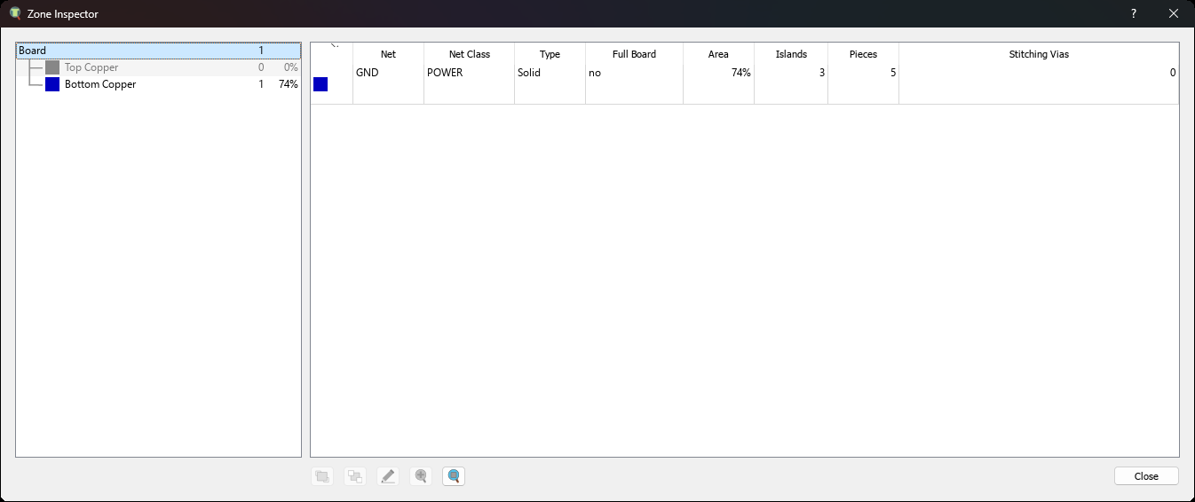
Zone Inspector in Board View. The data grid shows data about all planes on the layout.
For a lot of designers Zone Inspector will prove to be a commonly used tool and it will be useful to assign to a keyboard shortcut. You can do this via the Set Keyboard Mapping command on the System Menu.
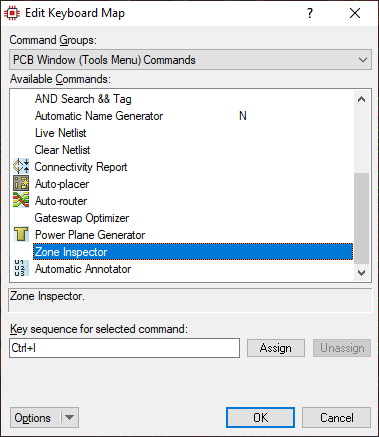
Setting the Zone Inspector to launch on the 'CTRL+I' keyboard shortcut.
Locating Planes on the Layout
The layer stackup appears on the left hand side of the dialogue. Layers with no planes are disabled / greyed out and all other layers are selectable. The data grid on the right hand side then lists the planes on the current scope. By default this is the complete board but you can filter the results by clicking on one of the enabled layers. This will restrict the data grid to the planes on the selected layer and will also switch the editing window to show only the planes on that layer.
You can then locate a plane simply by selecting it in the data grid. If it hasn't done already the Editing Window will change to remove all other layers and the plane you have selected will be highlighted on screen.
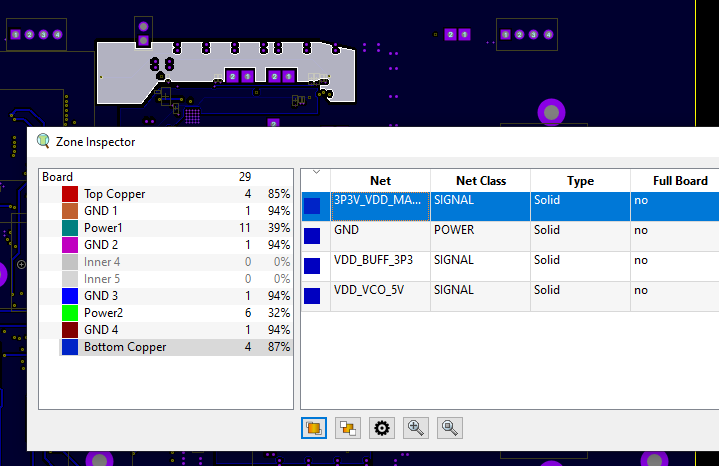
The currently selected plane is highlighted and the other layers switched off for easier viewing.
If the plane is very small or you want to inspect in more detail you can use the Zoom in to zone button underneath the data grid to step incrementally to higher magnification.
There are five buttons underneath the data grid, identified by their tooltips: Move zone to front, Move zone to back, Edit zone, Zoom in to zone and Zoom to board. Zoom to board is the way back out to the whole layout after you have zoomed in on a small plane.
Inspecting Plane Configurations
The data grid contains lots of useful information about the planes on the board/layer:
Layer
The coloured square is a layer indicator and matches the colour used on the layout and as shown in the Layer Selector on the left. This is the default ordering column ensuring that planes are grouped by layer when in full board view.
Net
Lists the net that a given plane is assigned to.
Net Class
Lists the net class that a given plane is assigned to.
Type
Specifies the type of the plane. The five values are Solid, Hatch (diagonal), Hatch (axial), Empty and Compatible. Note that the Edit Zone dialogue offers only four types, because there hatching is a single Hatched type with a separate Diagonal checkbox. The inspector splits the two apart for display, which is why the two dialogues appear to list different numbers of types.
Full Board
Indicates whether the plane has been set to cover the full board. This can either be done at the point of layer stackup by defining a plane layer or via the lock to board edge option on the Edit Zone dialogue after placement.
Area
The percentage of the board area that is occupied by the plane. This will be an approximation, since relief spokes on thermal connections are not counted. If you want the per-layer figure rather than the per-board one, it is shown against each layer in the tree on the left hand side.
Islands
Specifies the number of islands on the plane. An island is a piece (see below) that has no connectivity. Often they are therefore considered redundant and can be suppressed via the option on the zone dialogue form.
Pieces
Specifies the number of pieces that the zone has been splintered into following placement. For example, a track running through the plane will split it into two pieces and the routing to an IC may leave sliver pieces in between the pins. You can think of this column as an indication of how badly the zone integrity has been affected by the rest of the layout.
Stitching Vias
When a plane has been stitched automatically (via the zone stitching or zone shielding commands) this column will display the number of vias used for the stitching or shielding.
An Empty zone shows a dash rather than a number in the Islands, Pieces and Stitching Vias columns. Empty zones are skipped by regeneration and by stitching, so there is nothing to count. This is worth knowing if you order the grid by Pieces to find the worst degraded planes and wonder why the empty zones sort oddly.
Note that you can re-order the data according to any column you like by clicking on that column. For example, on board view you may choose to order by net instead of layer. That would then group all the GND and VCC planes beside each other on the data grid making for easier inspection.
You can also move up and down the data grid with the up and down arrow keys on the keyboard providing a really easy way to cycle through planes, viewing them on the layout.
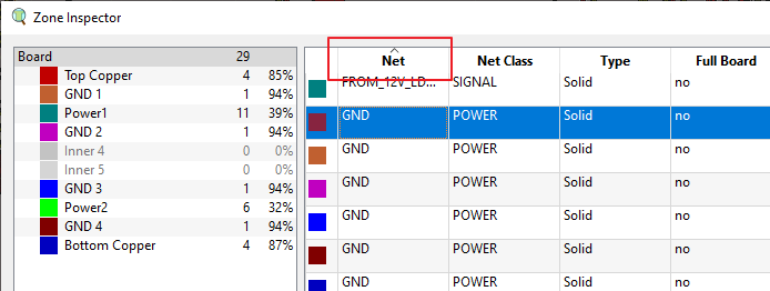
Ordering the Data Grid by Net.
Similarly, some columns such as Pieces provide insight into the effect of placement and routing on the plane. Ordering by this column will quickly show which planes have degraded the most.
In addition to ordering the data by column you can also re-order the columns themselves to show the most interesting data to you on the visible dialogue form. This lets you control the size of the dialogue form and prioritise the most relevant information on the screen.
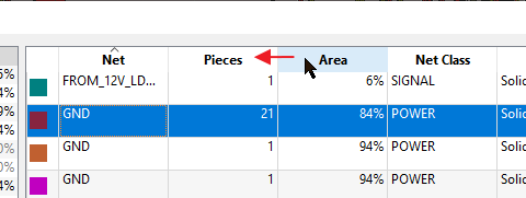
Changing column order to prioritise different data allows sizing down the dialogue.
Editing Plane Configuration
You can edit a plane at any time by
- Selecting the plane in the data grid.
- Clicking on the Edit zone button underneath the data grid.
Double clicking a row in the data grid does the same thing, which is quicker once you know it is there.
This can sometimes be a faster and more convenient method to edit than via the zone edge (see Editing a Power Plane).
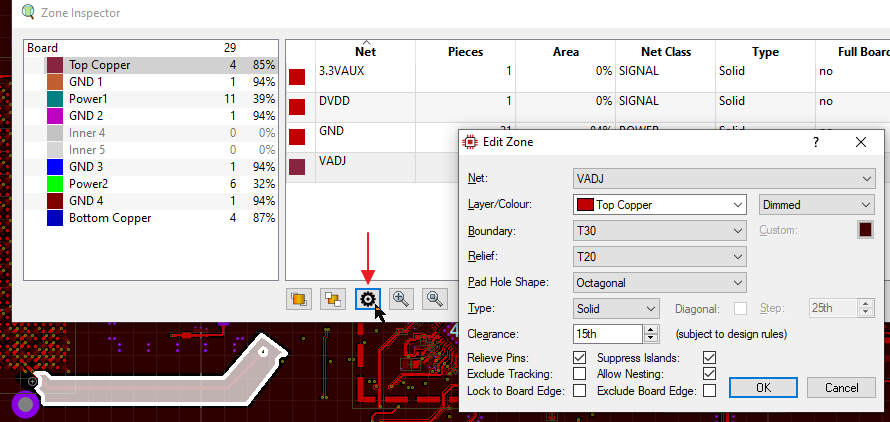
Editing Plane Configuration
Changing Plane Priority
This is a situation which occurs infrequently but is nonetheless quite important. Consider the highlighted plane below and notice in particular that it punches out part of an adjacent plane on a different net.
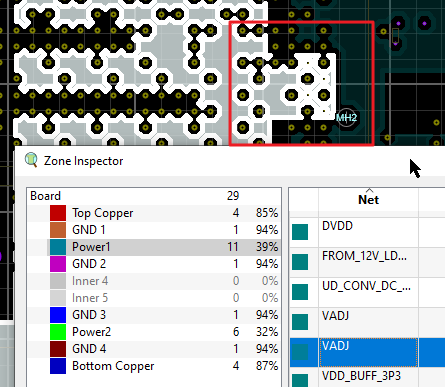
This plane punches out part of the adjacent plane.
The reason it does this - rather than the other plane punching out a part of this one - is draw order. The plane at the front punches out the one at the back. So, if we wanted this to work the other way around we could either move this one to the back or move the adjacent plane to the front. This is done via the two buttons underneath the data grid.
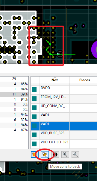
Move this plane to the back and now the adjacent plane punches out of this one.
An easy way to think of it is:
- Bring to front = punch out of the other planes.
- Move to back = walk around the other planes.
There is one exception to this rule. An Empty zone always punches the zones it overlaps, whatever its position in the draw order, because punching a void is the only thing an Empty zone does. Moving an Empty zone to the back will not make the other planes flood through it.
See Also: